Getting Started with Digital Systems Design Using F1 FPGAs
The second part of lab1 we will be translating Spatial code to Vitis C++ code. Vitis is a complete development environment for applications accelerated using Xilinx FPGAs. It leverages the OpenCL heterogeneous computing framework to offload compute intensive workloads to the FPGA. The accelerated application is written in C/C++, OpenCL, or RTL with OpenCL APIs. For the purpose of lab 1, all the exercises done with Spatial have been converted to C/C++ HLS. Lab1, part 2 will walk you through setting up an environment for running hardware emulation, generating the F1 instance bitstream, and running on the FPGA.
Table of Contents
- Getting Started with Digital Systems Design Using F1 FPGAs
- Prerequisite (Need to do them only once)
2.1 Setting up X11 Forwarding
2.2 Creating Alarm for you instance - Running hardware emulation and FPGA instance
- Understanding Lab1Part2DramSramExample Vitis HLS code
4.1 Understanding Vitis C++ code
4.2 Section A: create test data in the host memory (host.cpp)
4.3 Getting the device and kernel ready (host.cpp)
4.4 Section B: allocate DRAM in Global Memory (host.cpp)
4.5 Section C: Invoke the kernel (host.cpp)
4.6 Section D: Bring back results from DRAM (host.cpp)
4.7 Section E: Compare with gold (host.cpp) - Your Turn:
- Submission:
- Additional Materials for Vitis C++
Prerequisite (Need to do them only once)
- You should have received an email with a subject “[EE109] AWS Instance Instructions”. Download the private key attached to the email and save it under your
.sshfolder. Your path to the.sshfolder is usually:- Linux / Mac :
~/.ssh - Windows:
\Users\$USERNAME\.sshor\user\$USERNAME\.ssh(replace the $USERNAME with your laptop’s username)
- Linux / Mac :
- Sign into the AWS account using the link and information in the email. It will require you to change your password if it’s your first time logging in.
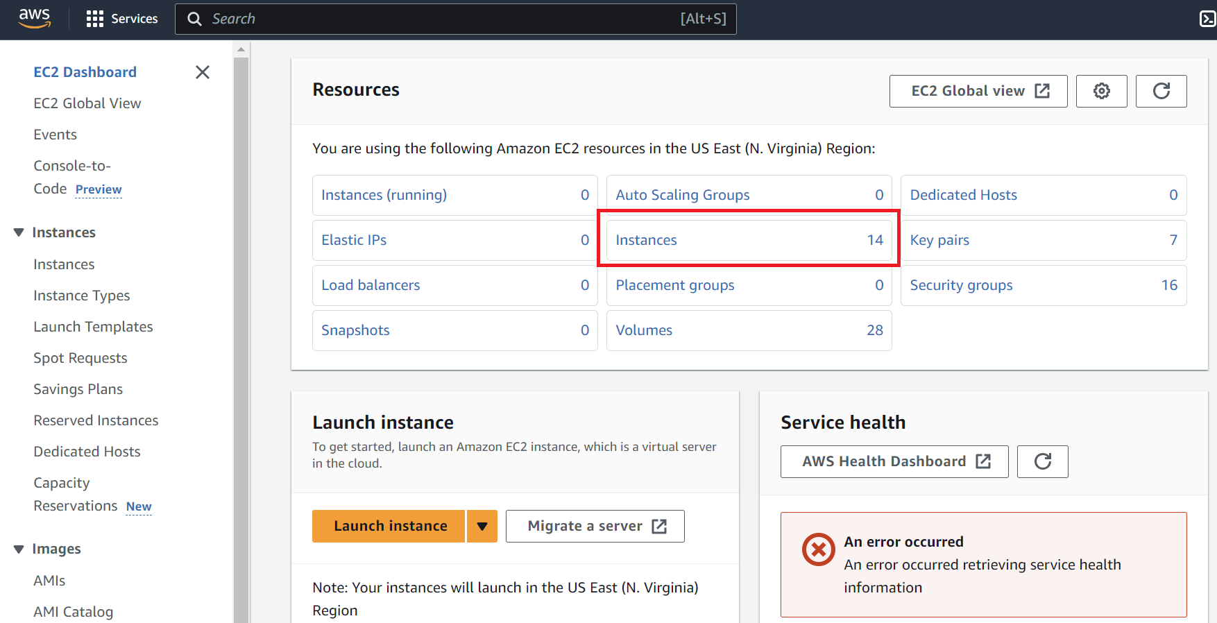
- Once you’re logged in, search for the ‘ec2’ service. If you click on EC2, this will bring you to the screen below. Press ‘Instances’.
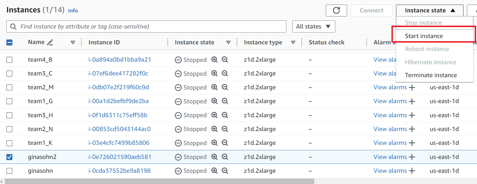
- Select your instance and go to Instance State > Start instance. The designated instance is stated in the email with the AWS login instructions.
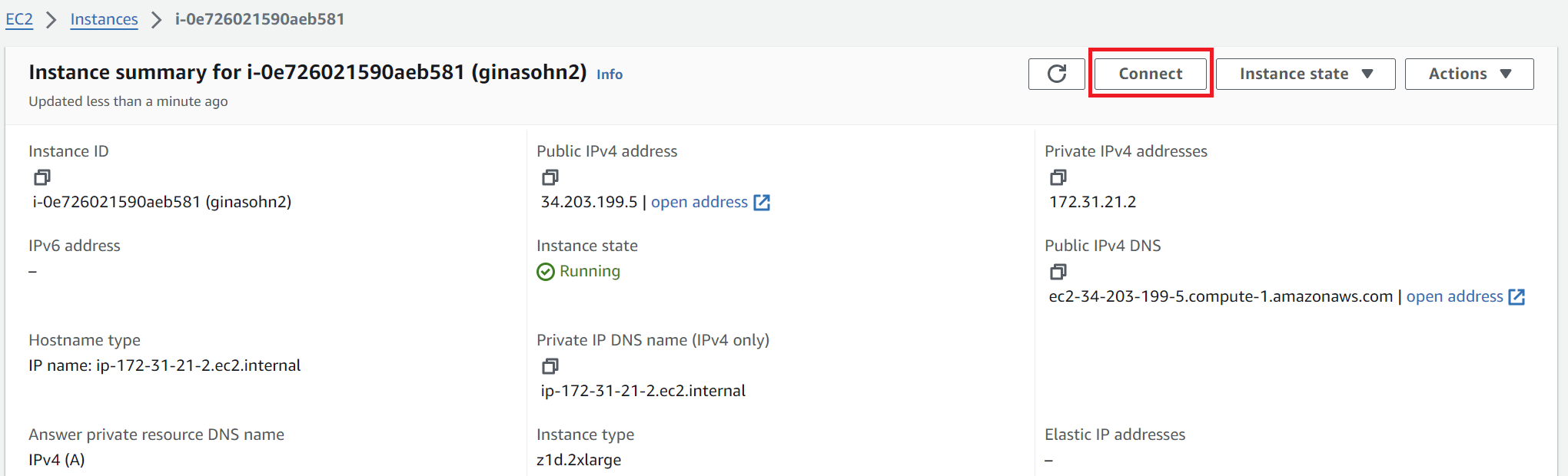
- Click the ‘Instance ID’ and press ‘connect’.
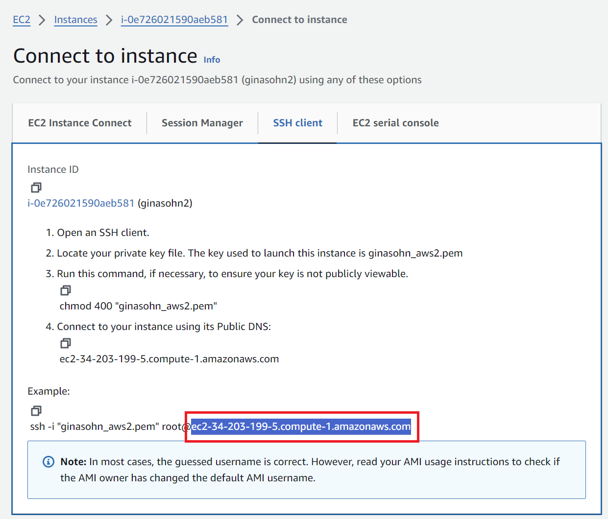
Move to the ‘SSH Client’ tab and copy the address shown in the boxed field in this picture. This address changes whenever you start the instance.
- SSH into your instance
-
Option 1: VSCode (We recommend this option when you edit code & run sw/hw emulations)
- Install the ‘remote-ssh’ extension
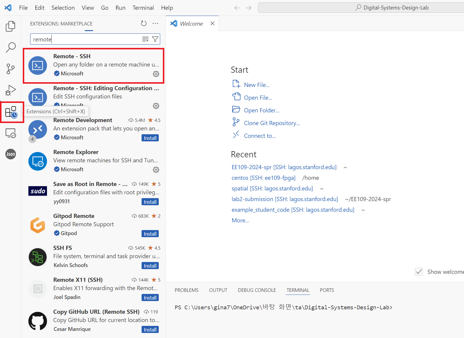
- Press the small button on the lower right and select Connect to host > Configure SSH Hosts and choose the first file (this will look something like
\user\$USERNAME\.ssh\config).
- Add the following entry to the file and save it. The value for
HostNameis the address you copied in step 5. This address changes whenever you start the instance. So you will have to update this field whenever you stop and re-start the instance. The ‘IdentityFile’ field is the location where you saved the private key file in step 1. In the screenshot shown in step 5, it uses ‘root’ as the user name, but use ‘centos’ instead.Host ee109-vitis HostName ec2-34-203-199-5.compute-1.amazonaws.com User ubuntu IdentityFile "C:\Users\gina7\.ssh\ginasohn_aws2.pem" - Go back and press the small button on the lower right you clicked in step 6-2 and select Connect to host. The host you’ve just added will now appear. Selecting the newly added AWS host will connect you to your instance. Once you’re connected, you can open folders in your instance using the ‘File > Open Folder’ feature and run code using the ‘Terminal > New Terminal’ feature.
- Install the ‘remote-ssh’ extension
-
Option 2: Terminal (We recommend this option when you want to open a gui to view the emulation reports) The value after the
-ioption is the location of the private key.ssh -i \Users\gina7\.ssh\ginasohn_aws2.pem ubuntu@ec2-34-203-199-5.compute-1.amazonaws.com
-
- Install packages (Paste the command one by one)
sudo apt update sudo apt install libxtst6 sudo apt install x11-apps sudo apt install xauth sudo apt install xfonts-base sudo apt install x11-utils - Clone the
aws-fpgagithub repository and setup the required XRT installations. Note that this step will take close to 30 minutesgit clone https://github.com/aws/aws-fpga.git $AWS_FPGA_REPO_DIR cd $AWS_FPGA_REPO_DIR git switch f1_xdma_shell source vitis_setup.sh XRT_RELEASE_TAG=202410.2.17.319 cd $VITIS_DIR/Runtime export XRT_PATH="${VITIS_DIR}/Runtime/${XRT_RELEASE_TAG}" git clone http://www.github.com/Xilinx/XRT.git -b ${XRT_RELEASE_TAG} ${XRT_PATH} cd ${XRT_PATH} sudo ./src/runtime_src/tools/scripts/xrtdeps.sh cd build ./build.sh cd Release sudo apt install ./xrt_*.deb - Setup CLI and create S3 bucket for creating Amazon FPGA Image (AFI)
- CLI Setup
cd ~/ curl "https://awscli.amazonaws.com/awscli-exe-linux-x86_64.zip" -o "awscliv2.zip" unzip awscliv2.zip sudo ./aws/install # Use --update if the command output tells you to - Check if it’s properly installed by running:
aws --version - Set your credentials, region and output. If you run the following command, it will ask you for Access Key ID and Secret Access Key which can be found in the email sent to you with the title “[EE109] AWS F1 resource”. For the region, write ‘us-east-1’ and for the output write ‘json’.
aws configure - The result should look like:
[centos@ip-172-31-21-2 src]$ aws configure AWS Access Key ID [None]: <Your Access Key> AWS Secret Access Key [None]: <Your Secret Access Key> Default region name [None]: us-east-1 Default output format [None]: json - S3 bucket creation (You should go through this process whenever you want to make a new S3 bucket). This S3 bucket will be used by the AWS scripts to upload your DCP to AWS for AFI generation which will be packaged into a tar file. Start by creating a bucket. Bucket names must be between 3 (min) and 63 (max) characters long. Bucket names can consist only of lowercase letters, numbers, dots (.), and hyphens (-). As a bucket name has to be unique, we recommend including your user name. For example, I used
psmritito run the lab 1 parts.aws s3 mb s3://<bucket-name> --region us-east-1 # Create an S3 bucket (choose a unique bucket name) touch FILES_GO_HERE.txt # Create a temp file aws s3 cp FILES_GO_HERE.txt s3://<bucket-name>/<dcp-folder-name>/ # Choose a dcp folder name - The AFI creation process will generate logs and will be placed in your S3 bucket. These logs can be used for debug if the AFI generation fails. Next, create a folder for your log files:
touch LOGS_FILES_GO_HERE.txt # Create a temp file aws s3 cp LOGS_FILES_GO_HERE.txt s3://<bucket-name>/<logs-folder-name>/ # Choose a logs folder name - Once your AFI has been created successfully, you are free to delete the tar file and logs as needed. Deleting these files will not delete or modify your AFI.
- CLI Setup
Setting up X11 Forwarding
To view the emulation results, using the vitis analyzer’s gui will be useful. However, to use a gui when working with a remote server, you will have to set up X11 forwarding. X11 forwarding is a mechanism that allows a user to start up remote applications, and then forward the application display to their local machine.
For Mac users, follow the ‘X11 forwarding for Mac’ section in this link.
For Window users, follow these steps:
- Install PuTTy on your local Windows machine: Download the installer & run it
- Install Xming on your local Windows machine: Download the installer & run it
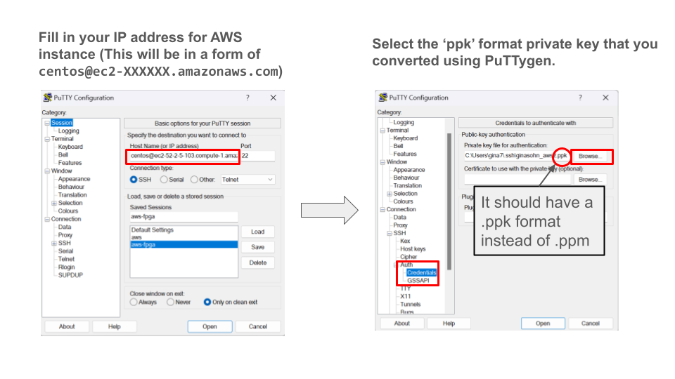
- Convert your private key from a pem format to a ppk format using PuTTygen. Follow the instructions in this link.
-
Open PuTTy and follow these steps to ssh into your instance. Make sure to change
centostoubuntu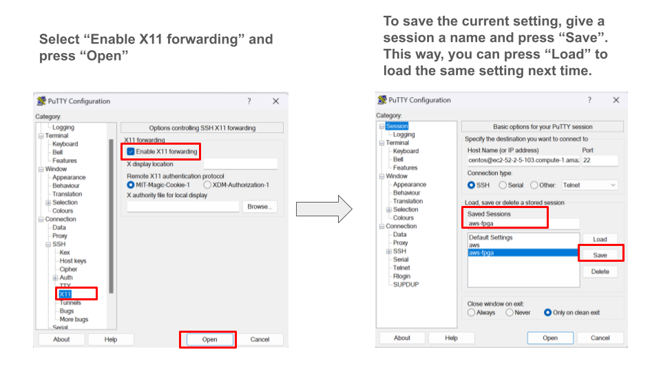
- Activate xming.
- Run this command in your instance. If you see a clock showing up, you’re all set.
xclock
Creating Alarm for you instance
AWS instances: We will soon set up a AWS credit limitation for each student. We are planning to allocate $200 − $250 for each student to cover the labs and the final project. We will announce more detailed information about this soon. However, in the meanwhile, please make sure you stop your instances after using it so that you don’t mistakenly use up all your credits!!
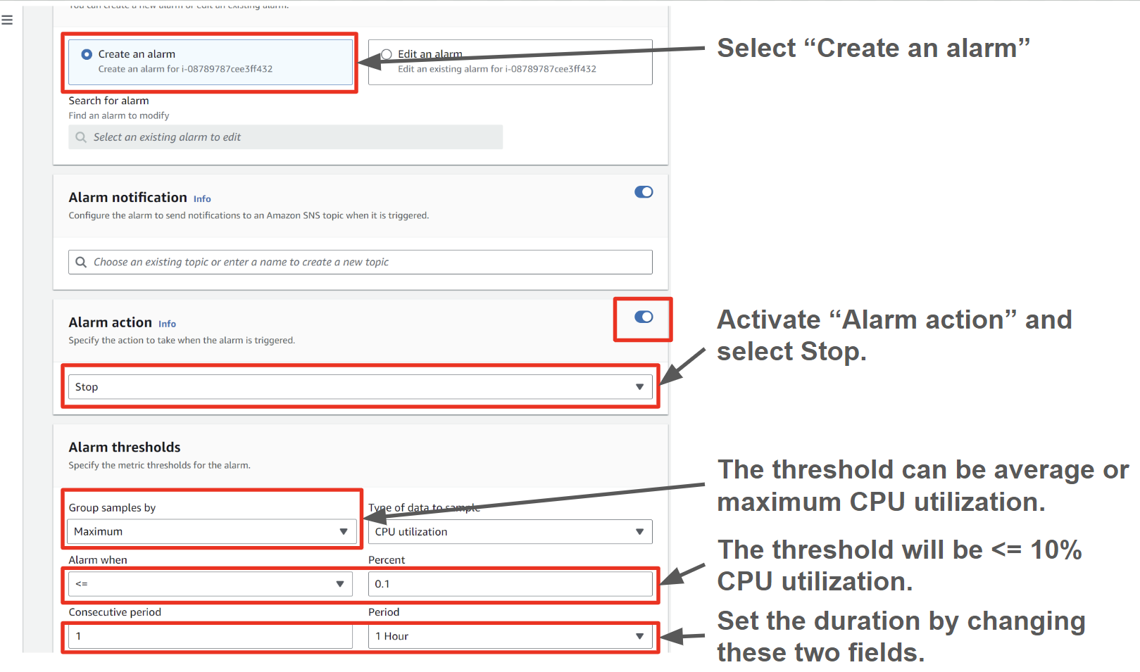
To prevent such issues, we highly recommend setting up an alarm to stop the instance after a certain duration of low usage.
To set up the alarm, select the + button for your instance.
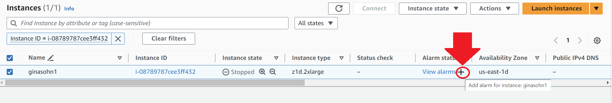
Then follow the instructions in this screenshot. This will be an example configuration for setting an alarm to stop the instance after the maximum CPU utilization was lower than 10% for more than an hour.
Running hardware emulation and FPGA instance
-
Accept the assignment in Github Classroom and clone your Lab1 directory.
- Copy the
Lab1Part1RegExamplefolder to the Vitis xilinx folder.cp -rf $LAB1_DIR/Lab1Part1RegExample $AWS_FPGA_REPO_DIR/Vitis/examples/xilinx/ - Source vitis_setup.sh
cd $AWS_FPGA_REPO_DIR/ source vitis_setup.sh cd $VITIS_DIR/examples/xilinx/Lab1Part1RegExample - Run hardware emulation (this might take about 10-15 minutes)
# Hardware Emulation (Compile and runtime ~10 mins) make clean make run TARGET=hw_emu PLATFORM=$AWS_PLATFORM all # You should see a TEST PASSED print at the end - Generate bitstream for running on FPGA (bitstream generation takes about 1 hour 40 mins)
make clean make TARGET=hw PLATFORM=$AWS_PLATFORM all - Generating AFI image
$VITIS_DIR/tools/create_vitis_afi.sh -xclbin=build_dir.hw.xilinx_aws-vu9p-f1_shell-v04261818_201920_4/vadd.xclbin -o=vadd -s3_bucket=<bucket-name> -s3_dcp_key=dcp-folder -s3_logs_key=logs-folderAfter running the above step, check the status of the
FpgaImageId. Wait till status turns available from pending to proceed further. This will take about 15 minutes to generate the AFI.ubuntu@ip-172-31-89-122:~/src/project_data/aws-fpga/Vitis/examples/xilinx/Lab1Part1RegExample$ cat 25_04_06-080556_afi_id.txt { "FpgaImageId": "afi-0e16cc800ad7049f1", "FpgaImageGlobalId": "agfi-00851c94144a3bc55" } ubuntu@ip-172-31-89-122:~/src/project_data/aws-fpga/Vitis/examples/xilinx/Lab1Part1RegExample$ aws ec2 describe-fpga-images --fpga-image-ids afi-0e16cc800ad7049f1 { "FpgaImages": [ { "FpgaImageId": "afi-0e16cc800ad7049f1", "FpgaImageGlobalId": "agfi-00851c94144a3bc55", "Name": "vadd", "Description": "vadd", "ShellVersion": "0x04261818", "PciId": { "DeviceId": "0xf010", "VendorId": "0x1d0f", "SubsystemId": "0x1d51", "SubsystemVendorId": "0xfedd" }, "State": { "Code": "available" }, "CreateTime": "2025-04-06T08:06:01+00:00", "UpdateTime": "2025-04-06T08:44:48+00:00", "OwnerId": "891377270430", "Tags": [], "Public": false, "DataRetentionSupport": false, "InstanceTypes": [ "f1.2xlarge", "f1.4xlarge", "f1.16xlarge" ] - Running the generated AFI
 cd $AWS_FPGA_REPO_DIR
 source vitis_runtime_setup.sh   # Other runtime env settings needed by the host app should be setup after this step
 # Wait till the MPD service has initialized. Check systemctl status mpd
 cd $VITIS_DIR/examples/xilinx/Lab1Part1RegExample
 ./Lab1Part1RegExample ./vadd.awsxclbin
 # You should see a TEST PASSED print at the end
Expected output:
 ubuntu@ip-172-31-89-122:~/src/project_data/aws-fpga/Vitis/examples/xilinx/Lab1Part1RegExample$ ./Lab1Part1RegExample ./vadd.awsxclbin
 Found Platform
 Platform Name: Xilinx
 INFO: Reading ./vadd.awsxclbin
 Loading: './vadd.awsxclbin'
 Trying to program device[0]: xilinx_aws-vu9p-f1_shell-v04261818_201920_3
 Device[0]: program successful!
 TEST PASSED
Understanding Lab1Part2DramSramExample Vitis HLS code
In this walkthrough, we will be comparing Vitis C++ code to the Lab1Part2DramSramExample code in Spatial. We will be multiplying x to a DATA_SIZE-long 32bit integer vector.
Let’s assume the datawidth between the on-chip and off-chip transfer is 512 bits. We will load NUM_WORDS number of elements from DRAM to SRAM in parallel (this is similar as loading in a NUM_WORDS-long vector). It will then do an element-wise multiplication for the NUM_WORDS elements in parallel and store it back to DRAM. This process will be sequentially repeated until all the DATA_SIZE elements are computed (iterations of the outer loop will not be pipelined due to the Sequential directive in front of the Foreach controller).
Understanding Vitis C++ code
Now we will look at the Vitis C++ code for the same application. The code can be found under Lab1Part2DramSramExample/src in Lab1’s directory. host.cpp describes the behavior of the host and the accelerator design is specified in vadd.cpp which is the equivalent to the Accel block in Spatial.
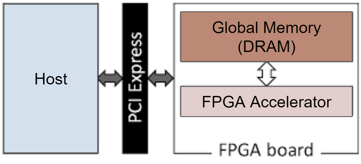
When accelerating applications with FPGAs, there are four major components. Host, Global Memory (DRAM), the on-chip memory and logic on the FPGA accelerator.
Section A: create test data in the host memory (host.cpp)
The first step is to create test data in the host memory. If you are not familiar with std::vector, please read this.
// host.cpp
std::vector<int, aligned_allocator<int>> source_in1(DATA_SIZE);
std::vector<int, aligned_allocator<int>> source_hw_results(DATA_SIZE);
std::vector<int, aligned_allocator<int>> source_sw_results(DATA_SIZE);

// Create the test data
std::generate(source_in1.begin(), source_in1.end(), std::rand);
int x = 5;
for (int i = 0; i < DATA_SIZE; i++)
{
    source_sw_results[i] = x * source_in1[i] ;
    source_hw_results[i] = 0;
}
Getting the device and kernel ready (host.cpp)
The code in this region upto section D will program the device and run the FPGA accelerator. To do this, it will use several OpenCL C++ Bindings such as cl::Program, cl::Context, cl::CommandQueue, cl::Kernel.
The first step is to get the list of devices connected to the Xilinx platform.
auto devices = xcl::get_xil_devices();
Then it will get the binary file of the kernel to run. To learn more about cl::Program::Binaries, read:
cl::Program- OpenCL C++ doc page 28
auto fileBuf = xcl::read_binary_file(binaryFile);
cl::Program::Binaries bins;
In the following for loop, the Context and Command Queue are created for the device.
- Reference:
cl::Context- OpenCL C++ doc page 6
cl::CommandQueue- OpenCL C++ doc page 47
OCL_CHECK(err, context = cl::Context(device, nullptr, nullptr, nullptr, &err));
OCL_CHECK(err, q = cl::CommandQueue(context, device, CL_QUEUE_PROFILING_ENABLE, &err));
Then, it tries to program the selected device using the binary of the kernel.
- Reference:
cl::Program- OpenCL C++ doc page 28
cl::Kernel- OpenCL C++ doc page 36
cl::Program program(context, {device}, bins, nullptr, &err);
if (err != CL_SUCCESS)
{
  std::cout << "Failed to program device[" << i << "] with xclbin file!\n";
}
else
{
  std::cout << "Device[" << i << "]: program successful!\n";
  OCL_CHECK(err, krnl_vector_op = cl::Kernel(program, "vadd", &err));
  valid_device = true;
  break; // we break because we found a valid device
}
Section B: allocate DRAM in Global Memory (host.cpp)
Then, we allocate DRAM that will hold the input vectors and the output vector in Global Memory. The DRAMs are initialized with the vectors created in section A. To express DRAMs in Global Memory, we will use OpenCL Buffers. buffer_in1 and buffer_in2 will be the DRAMs that store the input vectors and the output will be stored in buffer_output DRAM.
// Allocate Buffer in Global Memory
// Buffers are allocated using CL_MEM_USE_HOST_PTR for efficient memory and
// Device-to-host communication
OCL_CHECK(err, cl::Buffer buffer_in1(context, CL_MEM_USE_HOST_PTR | CL_MEM_READ_ONLY, vector_size_bytes,
                                        source_in1.data(), &err));
OCL_CHECK(err, cl::Buffer buffer_output(context, CL_MEM_USE_HOST_PTR | CL_MEM_WRITE_ONLY, vector_size_bytes,
                                        source_hw_results.data(), &err));
We have created the kernel that will run on the FPGA accelerator (krnl_vector_op) in this section. We will set the arguments for this kernel now.
int size = DATA_SIZE;
OCL_CHECK(err, err = krnl_vector_op.setArg(0, buffer_in1));
OCL_CHECK(err, err = krnl_vector_op.setArg(1, x));
OCL_CHECK(err, err = krnl_vector_op.setArg(2, buffer_output));
OCL_CHECK(err, err = krnl_vector_op.setArg(3, size));

// Copy input data to device global memory
OCL_CHECK(err, err = q.enqueueMigrateMemObjects({buffer_in1}, 0 /* 0 means from host*/));
Section C: Invoke the kernel (host.cpp)
Finally, we will invoke the HLS kernel so the program can run on the FPGA accelerator.
// Launch the Kernel
// For HLS kernels global and local size is always (1,1,1). So, it is
// recommended
// to always use enqueueTask() for invoking HLS kernel
OCL_CHECK(err, err = q.enqueueTask(krnl_vector_op));
Section D: Bring back results from DRAM (host.cpp)
Then, the we will bring back the results from the output DRAM in global memory (buffer_output) to the host memory.
OCL_CHECK(err, err = q.enqueueMigrateMemObjects({buffer_output}, CL_MIGRATE_MEM_OBJECT_HOST));
q.finish();
Section E: Compare with gold (host.cpp)
Since we are done working with the FPGA accelerator, there will be no OpenCL C++ bindings from this section and will only be C++. The results will be stored in the source_hw_results and we compare this with the gold source_sw_results we have computed in section A.
Your Turn:
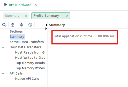
- Run hardware emulation for Lab1Part1RegExample, Lab1Part2DramSramExample, Lab1Part4FIFOExample and Lab1Part6ReduceExample and report the runtimes in
lab1_submit.md. They can be found in the ‘profile summary’ tab in the `xrt.run_summary’ file. You can open this with a gui (note that this needs the X11 forwarding setup) by running:cd $VITIS_DIR/examples/xilinx/Lab1Part1RegExample vitis_analyzer --classic xrt.run_summary
- Generate bitstream, create AFI image and run F1 instance for Lab1Part1RegExample. Submit the
vadd.awsxclbinin the submission. - Compare Lab1Part1RegExample, Lab1Part2DramSramExample, Lab1Part4FIFOExample and Lab1Part6ReduceExample’s
host.cppandvadd.cppwith the respective .scala implamentation and add your inferences to thelab1_submit.md
Important Notes -
- Because of limited disk space, you will run out of space intermittently. It is recommended that you clean up as you go and save the important files (like vadd.awsxclbin and other .csv files). Feel free to clean up the build_dir, _x.hw.* and _x.hw_emu* directory once your are done running them and see a
TEST PASSEDprint. - Don’t forget to add the submission files to your lab1 directory! We will grade using your lab1 directory, so make sure you copy your required files from the AWS FPGA repo to your lab1 repository and push them.
- The kernel execution time and compute unit utilization can also be found in the ‘profile summary’ tab in the `xrt.run_summary’ file. But there seems to an issue with the current setup and is under debug
Submission:
- Gradescope: a doc with your commit ID & repo
- Lab 1 Part 1: Leave your implementation under your Github Classroom repository’s
src/test/scala/Lab1.scalafile. - Lab 1 Part 2:
- Lab1Part1RegExample - Submit the generated AFI image to the your Github Classroom repository’s
Lab1Part1RegExample/ - Lab1Part1RegExample, Lab1Part2DramSramExample, Lab1Part4FIFOExample and Lab1Part6ReduceExample add hw_emu’s summary.csv to the your Github Classroom repository’s
Lab1Part1RegExample,Lab1Part2DramSramExample,Lab1Part4FIFOExampleandLab1Part6ReduceExamplerespectively
- Lab1Part1RegExample - Submit the generated AFI image to the your Github Classroom repository’s
- Fill in your Github Classroom repository’s
lab1_submit.md
Additional Materials for Vitis C++
This is a very simplified example to introduce how to develop hardware with Vitis and show how we can translate Spatial code to Vitis C++ code. There are many other ways to make this code better.
- dataflow pragma: The dataflow pragma instructs the compiler to enable task-level pipelining. This is required for load/compute/store functions to execute in a parallel and pipelined manner. The new implementation of the same application using dataflow pramas can be found here.
- Various example kernels: The Vitis repository has a series of example kernel implementations, which can be a useful reference.
- Vitis Unified Software Platform Documentation: This official documentation hold many useful information.
- Vitis HLS Command Reference: This will be useful to look up HLS pragmas and HLS data types (these will start with a
hls::prefix in the code). - Quick Start Guide